")
")


So, how do you do that: re-design?
Here and on the next pages Pim explains how he works, and why he uses three-dimensional design software.
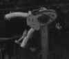
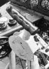
Let us take a relatively simple component about which pretty much information is available: the steering column. Of course the information I get comes from photo material!
 |
 |
 |
 |
 |
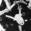
But sometimes I have the luxury of a drawing or a sketch like this:
Thus , all the information is available. Or not? Often it happens that new pictures and / or drawings are found that makes redesign easier.
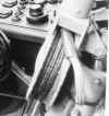
If I have only photographs available I have to estimate the size of the component on basis of items from that same picture and of which I do know of all the dimensions.
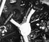
Then the real work starts. Normally I start sketching the part in a flat perspective. Then I 'm going to shapen the part. Then, by making the holes and subtracting them from the part. Sometimes it is just like making the real part : First, a large piece of material and then drilling / milling / cutting holes in it. See animation below to reflect the operations.
After all the 3D work has been done, we can start drawing. For simple parts a drawing is still the easiest way to get something manufactured.
First we select the item we want to design and indicate the direction from which comes the first view (below you see the front view). The computer now calculates what must be printed be on paper.
Still a few clicks on the mouse and we have the other two views. Dimensioning the drawing must still be done by hand, although the value/length/diameter is generated by the program. The "designer" only need to indicate which lines he wants to resize. The result is shown below.
For making this drawing, including resizing, I needed approximately 10 minutes.
Nothing is certain in the design process, especially if one has to start from only photos to design from.
The power of the 3D design is not in the making of a drawing, but to the easy way of applying changing to the design. For instance, the ball-bearing that is needed in the middle of the steering column has a different diameter than imagined. We go into the 3D model and choose the cylinder needed for the bearing. The software program (here CATIA V4) shows the size of the hole:
We select "R1 = 20.000" and then we type "30" and voila!
Now the drawing , we instruct the computer to refresh the views and voila!